Description
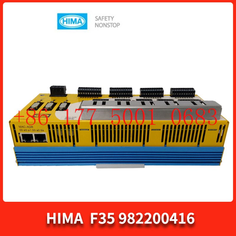
Bv7048 HIMA DO digital output
Bv7048 HIMA DO digital output
Module Clips Drive controller servo motor
Contact: Mr. Lai
Wechat:17750010683
Whats app:+86 17750010683
Skype:+86 17750010683
QQ: 3221366881
3221366881@qq.com
The most widely used regulator control in practice is proportional, integral, and differential control, abbreviated as PID control or PID regulation. PID regulation has become one of the main technologies in industrial control due to its simple structure, good stability, reliable operation, and convenient adjustment. When the structure and parameters of the controlled object cannot be fully mastered or precise numbers cannot be obtained. When learning models, when other techniques of control theory are difficult to adopt, the structure and parameters of the system controller must be determined through experience and on-site debugging. At this time, the application of PID control technology is the most convenient. When we do not fully understand a system and the controlled object, or cannot obtain system parameters through effective measurement methods, PID control technology is most suitable. PID control also includes PI and PD control in practice. The PID regulator is controlled by calculating the control quantity based on the system error using proportion, integration, and differentiation.
Scale Bv7048 HIMA DO digital output
Proportional control is the simplest control method. The output of its controller is proportional to the input deviation signal, which in simple terms is the input deviation multiplied by a coefficient. When there is only proportional control, there is a steady-state error in the system output.
Input deviation refers to the difference between the regulated quantity and the set value of the regulator.
Integral (I)
In differential control, the output Bv7048 HIMA DO digital output of the controller is directly proportional to the differential of the input deviation signal (i.e. the rate of error change). Generally speaking, integration refers to the integration operation of the input deviation. The automatic control system may experience oscillations or even instability during the adjustment process of overcoming errors. The reason is that there are large inertia components (links) or lag components that have the effect of suppressing errors, and their changes always lag behind the changes in errors. The solution is to make the change in the effect of suppressing error “advance”, that is, when the error approaches zero, the effect of suppressing error should be zero. That is to say, introducing only the “proportion” term in the controller is often not enough. The function of the proportion term is only to amplify the amplitude of the error, and what needs to be added at present is the “differential term”, which can predict the trend of error change. In this way, a controller with proportion+differential can make the control effect of suppressing error equal to zero or even negative in advance, thereby avoiding serious overshoot of the controlled quantity. Therefore, for controlled objects with significant inertia or lag, the proportional and differential (PD) controller can improve the dynamic characteristics of the system during the adjustment process.
Differential
In integral control, the output of the controller is directly proportional to the integral of the input deviation signal. Generally speaking, differentiation refers to the differential operation of the input deviation. For an automatic control system, if there is a steady-state error after entering the steady-state state, it is said to have steady-state error or simply a differential system. In order to eliminate steady-state errors, it is necessary to introduce an “integral term” in the controller. The error of the integration term depends on the integration of time, and as time increases, the integration term will increase. In this way, even if the error is small, the integral term will increase with time, driving the output of the controller to increase and further reducing the steady-state error until it equals zero. Therefore, the PI controller (proportional+integral) can ensure that the system has no steady-state error after entering steady state.
The PID parameter tuning formula states: “The ideal curve has two waves, with a front high and a back low ratio of 4 to 1.” This curve is essentially a problem with the quality indicators of the PID regulation system. Figure 1 is a familiar block diagram of the PID control system. Each block in Figure 1 represents a component of the control system, and the interrelationship and influence of each component in the system can be seen from the figure. The PID control system is a closed-loop system with negative feedback of the adjusted parameters. When the controlled quantity Y is affected by interference and rises, the feedback signal will be higher than the given value X. After comparison, the deviation signal e to the amplifying element will be negative, and the controller will send a signal to cause the executing element to act, with its direction of action being negative, causing the controlled quantity to decrease, thus achieving the purpose of automatic control.
Figure 1 Block diagram of PID regulation system
When the given and interference of a PID regulating system remain constant, the entire system is in a relative equilibrium state, where the measuring elements, amplifying regulating elements, and executing elements are temporarily inactive, and the output signal of the system is also in a relatively static state. The equilibrium state where the controlled quantity does not change with time is called the static state of the system. But due to the influence of interference, this equilibrium state is disrupted, and the controlled quantity will change. The PID regulator will change the adjustment parameters to overcome the influence of interference and strive to restore the system to its equilibrium state. From the occurrence of interference to the reestablishment of balance in the system, during this period, all links and parameters of the entire system are in a state of change, so this state is called dynamic. When the PID control system is dynamic, the controlled quantity is constantly changing. The process of it changing over time is called the transition process of the PID control system. That is, the process of the system transitioning from one equilibrium state to another; That is the process of constantly overcoming the influence of interference.
The basis for measuring the quality of a PID control system in design, tuning, and operation is the transition process of the system. When the input of the system undergoes a step change, the transition process of the system mostly manifests as an oscillation process, such as divergent oscillation, constant amplitude oscillation, attenuated oscillation, monotonic process, etc. But in most cases, it is desirable to obtain a transition process of attenuation oscillation, as it is used as a basis for measuring the quality of control systems.
Figure 2 Schematic diagram of quality indicators during the transition process of PID control system
Figure 2 is a schematic diagram of the quality indicators of the transition process, which is also the transition process under the influence of interference. When measuring system quality using transition processes, commonly used indicators include attenuation ratio, residual error, maximum deviation, transition time, oscillation period, and oscillation frequency.
Attenuation ratio
The attenuation ratio is the ratio of the two peaks before and after, conventionally expressed as n:1.
Residual difference
The residual deviation is the residual deviation at the end of the transition process, as shown in C
Maximum deviation
The maximum deviation is the peak value of the first wave, as shown in Figure A, and sometimes the overshoot is used to indicate the degree of deviation of the tuned parameter.
Transition time
The transition time is the period from the occurrence of interference to the establishment of a new equilibrium state for the adjusted parameter.
Oscillation period
The oscillation period is the time between the transition process from the first peak to the second peak.
Number of oscillations
The number of oscillations is the number of oscillations of the tuned parameter during the transition time.
The quality of a PID control system is mainly measured by the deviation of the controlled instrument from the given value after external interference. If the deviation can quickly and smoothly return to the given value, it is considered good. It is generally believed that the transition process shown in Figure 2 is the best and used as a measure of P İ Quality indicators for D control system work. The reason for choosing this curve as an indicator is that it returns to the given value faster for the first time, and although it deviates again, the deviation is not significant and stabilizes after a few oscillations. Quantitatively, the height of the first peak is four times that of the second peak, so this curve is also called a 4:1 attenuation curve. When tuning PID parameters, it is best to obtain a 4:1 decay transition process, and the PID control parameters at this time can be called the optimal parameters.
The ideal curve has two waves, with a front high and a back low ratio of 4 to 1 “refers to a curve like Figure 2, which means that the transition process can be stabilized by oscillating twice and has a attenuation ratio close to 4:1 after oscillating twice. It is considered the best transition process.
1.Has been engaged in industrial control industry for a long time, with a large number of inventories.
2.Industry leading, price advantage, quality assurance
3.Diversified models and products, and all kinds of rare and discontinued products
4.15 days free replacement for quality problems
ABB — AC 800M controller, Bailey, PM866 controller, IGCT silicon controlled 5SHY 3BHB01 3BHE00 3HNA00 DSQC series
BENTLY — 3500 system/proximitor, front and rear card, sensor, probe, cable 3500/20 3500/61 3500/05-01-02-00-001 3500/40M 176449-01 3500/22M 138607-01
Emerson — modbus card, power panel, controller, power supply, base, power module, switch 1C31,5X00, CE400, A6500-UM, SE3008,1B300,1X00,
EPRO — PR6423 PR6424 PR6425 PR6426 PR9376 PR9268 Data acquisition module, probe, speed sensor, vibration sensor
FOXBORO — FCP270 FCP280 FCM10EF FBM207 P0914TD CP40B FBI10E FBM02 FBM202 FBM207B P0400HE Thermal resistance input/output module, power module, communication module, cable, controller, switch
GE —- IS200/215/220/230/420 DS200/215 IC693/695/697/698 VMICPCI VMIVME 369-HI-R-M-0-0-E 469 module, air switch, I/O module, display, CPU module, power module, converter, CPU board, Ethernet module, integrated protection device, power module, gas turbine card
HIMA — F3 AIO 8/4 01 F3231 F8627X Z7116 F8621A 984862160 F3236 F6217 F7553 DI module, processor module, AI card, pulse encoder
Honeywell — Secure digital output card, program module, analog input card, CPU module, FIM card
MOOG — D136-001-007 Servo valve, controller, module
NI — SCXI-1100 PCI – PXIE – PCIE – SBRIO – CFP-AO-210 USB-6525 Information Acquisition Card, PXI Module, Card
Westinghouse — RTD thermal resistance input module, AI/AO/DI/DO module, power module, control module, base module
Woodward — 9907-164 5466-258 8200-1300 9907-149 9907-838 EASYGEN-3500-5/P2 8440-2145 Regulator, module, controller, governor
YOKOGAWA – Servo module, control cabinet node unit
Main products:
PLC, DCS, CPU module, communication module, input/output module (AI/AO/DI/DO), power module, silicon controlled module, terminal module, PXI module, servo drive, servo motor, industrial display screen, industrial keyboard, controller, encoder, regulator, sensor, I/O board, counting board, optical fiber interface board, acquisition card, gas turbine card, FIM card and other automatic spare parts


