")
Description
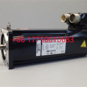
SH070/60030/0/1/00/00/00/01/00 Motor parameter settings
SH070/60030/0/1/00/00/00/01/00 Motor parameter settings
Module Clips Drive controller servo moto
SH070/60030/0/1/00/00/00/01/00A motor is a device that converts electrical energy into mechanical energy. SH070/60030/0/1/00/00/00/01/00 It utilizes an energized coil (i.e. stator winding) to generate a rotating
magnetic field and act on the rotor (such as a squirrel cage closed aluminum frame) to form a magneto electric rotational torque. Electric motors are divided into DC
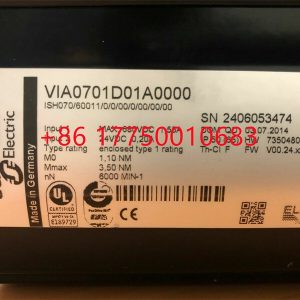
motors and AC motors according to the different power sources used. Most of the motors in the power system are AC motors, SH070/60030/0/1/00/00/00/01/00 which can be synchronous motors or
asynchronous motors (the stator magnetic field speed of the motor does not maintain synchronous speed with the rotor rotation speed). An electric motor is mainly
composed of a stator and a rotor, SH070/60030/0/1/00/00/00/01/00 and the direction of the force acting on the energized wire in the magnetic field is related to the direction of the current and the direction
of the magnetic induction line (magnetic field direction). SH070/60030/0/1/00/00/00/01/00 The working principle of an electric motor is that the magnetic field exerts a force on the current, causing the motor to rotate.
Contact: Mr. Lai
Wechat:17750010683
Whats app:+86 17750010683
Skype:+86 17750010683
QQ: 3221366881
3221366881@qq.com
2.3Smart component creation
Call the Rotator component: This component is used to allow the rotatable grinding rotor to rotate during simulation to simulate the real grinding scene. In the parameters of the Rotator component, set the reference to object, the reference object to the frame l, and the object to a copy of the rotor. (2) The rotary grinding rotor can be rotated, and the speed is l20mm/s (the speed of the grinding head will affect the quality of the finished product) ), the reference center axis is: axis (based on frame l, centerpoint x, y,: set to 0, 0, 0, Axis set x, y,: 0, 0, l000mm).
Call the Attach component: This component is used to allow the rotatable grinding rotor to be integrated with the tool body. When the tool body is installed on the flange, it can follow the movement of the flange. In the parameters of the Attach component, set the sub-object to be a copy of the rotor (2) for the rotatable polishing rotor, and the parent object is the tool body of a copy of the rotor. The offset and orientation are based on the offset of point B relative to the origin. For setting, you can use the measurement tool in Robotstudio software to measure, and then set the parameters after measurement.
Verification: Install a copy of the rotor tool body onto the robot flange, and then click Execute in the Attach component. You can observe whether the position of the rotatable grinding rotor is correct at this time. If there is a deviation, adjust the position in time, as shown in the figure. 5 shown.
Figure 5 Tool installation
2.4 Create tool coordinate system
Use the six-point method to create the tool coordinate system Too1data on the robot teach pendant at the center of the rotor. Change the tool coordinate system to Too1data in the basic options. At this time, click on the robot manual linear and you can drag the robot to move linearly at will.
2.5 Creating trajectories and programming
Determine the trajectory: According to the requirements of the work task, design the grinding trajectory around the workpiece and determine the trajectory points and transition points required for the grinding trajectory. The grinding action process is shown in Figure 6.
Setting I/O and programming: Yalong IY-l3-LA industrial robot deburring and grinding system control and application equipment adopts 0sDC-52 6/o communication board, the address is 10, Do1 is the digital output signal, the address is 1 . First set the I/O board, then set the I/O digital output signal Di1, and then program on the simulation teaching pendant. The procedure is as follows:
PRoCmain()
setDo1: Set the Do1 signal to allow the external grinding rotor to start rotating.
waitTime1: The robot stays in place and does not move, waits for 1s, and lets the polishing rotor turn to the specified speed, transition
MoveAbsjjpos10NoEoffs,v1000,z50,Too1data1: The robot moves to the initial point jpos10 above point p10. Point jpos10 is used as the starting point and end point of the robot’s action.
Move4p10,v1000,z50,Too1data1: Move straight line grinding to point p10
Move4pL0,v1000,z50,Too1data1: Move straight line grinding to pL0 point
Move4p30,v1000,z50,Too1data1: Move straight line grinding to point p30
Move4p40,v1000,z50,Too1data1: Move straight line grinding to p40 point
Move4p10,v1000,z50,Too1data1: Move straight line grinding to point p10
MoveAbsjjpos10NoEoffs,v1000,z50,Too1data1: The robot moves to the initial point jpos10 above point p10
waitTime1: wait 1s, transition
ResetDo1: Reset the Do1 signal to stop the rotor ENDPRoC
2.6 Simulation design and verification
Simulation design: Create a smart component to input the Di1 signal, and use the Di1 signal to simulate the external polishing start signal to execute the Rotator component and Attach component of the smart component to achieve the visual effect of rotating and polishing the polishing rotor. In the workstation logic design, the smart component input Di1 signal is associated with the robot Do1 signal, so that the robot signal Do1 can control the smart component input Di1 signal, thereby controlling the start and stop of the rotation of the polishing rotor.
Verification: In the program of the teaching pendant, first set the pp command to move to Main, and then set the robot startup mode to automatic. Click play in the simulation of Robotstudio software to verify whether the trajectory is consistent with the assumption, and optimize the path in time for problems existing in the simulation.
3Summary and outlook
This design is based on the programming simulation of the Yalong Y4-1360A industrial robot deburring system to control the grinding robot workstation. It covers aspects such as creating a workstation, setting up tools, creating smart components, creating tool coordinate systems, creating trajectories, programming, simulation design, and verification. Starting with it, the polishing simulation of the workstation is realized through the smart component function of Robotstudio software. The animation effect is intuitive and lifelike, which not only facilitates teaching demonstrations, but also facilitates program debugging, and has application value for both production and teaching.
In the planning and design of the workpiece grinding trajectory, according to the different roughness and grinding amount process requirements of the workpiece, the rotation speed, feed speed, feed amount, and grinding angle of the grinding rotor are also different. The feed amount can be adjusted in time according to the on-site conditions. , feed speed, rotor speed, grinding angle and other parameters. After appropriate adjustments, the motion trajectory is written with the corresponding program on the Robotstudio software to further reduce the possibility of robot collisions and singular points contained in the trajectory during the actual debugging process. ,Optimize paths and improve debugging efficiency.
GE IC697BEM713 Bus Transmitter Module (BTM)
GE IC697BEM711 Bus Receiver Module (BRM)
INTELLISCANDE14-405NM SCANLAB intelliSCAN scan heads
SQ-300I 8700700-006 Hybrid automatic voltage control (AVC)
CMA130 3DDE300410 ABB temperature controller
301131 PILZ Security bus module
T8111C ICS TRIPLEX Trusted TMR Processor
C2G170-24 P0973BL ENTERASYS network switch
PLATE F860-CA redundant fieldbus power
STK-RPS-150PS P0973BP Optical fiber interface board module
CLS216-10000000 WATLOW ANAFAZE CLS200 CONTROLLER
MT30R4-37 SEM D.C. Servomotors
SAI143-H53 Yokogawa Analog Input Module
DS200FCGDH1B Mark V Gate Distribution and Status Card FCGD
DS200VPBLG1A GE VME Backplane Board
DS200DDTBG1A LCI Auxiliary I/O Terminal Board
07DC92D GJR5252200R0101 Analog input and output module
2711P-B6C20D PanelView Plus 6 600 color terminal
FC-SDO-0824 V1.3 Safe Digital Output Module 24Vdc 0.55A 8ch
C200/10/1/1/100 ELAU programmable controller
PM866 3BSE050200R1 ABB PM866A controller
9905-973 Woodward controller turbine electric ship parts
TK-CCR014 HONEYWELL Redundant Net Interface Module
SLIO-02 ROLLS-ROYCE Controller module
ACR1000A-R2 Agility series optical fiber KVM wood extension
IRDH275B-435 Digital Ground Fault Monitor / Ground Detector
2098-DSD-020X/C Ultra 3000 Drive Module
BG65X50SI Dunkermotoren brushless DC motor
DPS112 MARITIME DGNSS SENSOR FOR WORLDWIDE OPERATIONS
MVI94-MCM-MHI PROSOFT Network Interface Module
VTR-5-PY DEIF Bridge wing indicator
DLQW72-PC-PY DEIF Marine bridge instrumentation
SPS5713 51199930-100 Power Transistor Devices
2301E 8273-1011 provides load sharing and speed control
VMIVME-7750-734001 ProcessorBased VME Single Board
SE3008 KJ2005X1-MQ2 13P0072X082 DeltaV™ SQ Controller
A6500-CC 9199-00120 System Communication Card
MVME761-001 MOTOROLA Transition Module
MVME2604761 I/O MOTOROLA single-board computer
VMIVME-7750-746001 ProcessorBased VME Single Board
TRICON 9566-8XX Terminal base
REF620E_F NBFNAAAANDA1BNN1XF Feeder protection and control
MVME51105E-2161 MOTOROLA single-board computer
SR489-P1-HI-A20-E-H GE generator management relay
531X302DCIAWG1 GE DC Instrumentation Card
PR6426/010-140+CON021 Eddy Current Signal Converter
8507-BI-DP PROFIBUS DP Bus Interface Module and Carrier
TRICON 4000093-510 External Terminal Input Cable Assembly
9907-147 ProTech 203 De-Energize-to-Trip Overspeed
VMIACC-5595-208 Reflective Memory Hub Assembly
PCD237A101 3BHE028915R0101 AC 800PEC control system
CI627A 3BSE017457R1 ABB controller module
TRICON 4000093-145 External Terminal Input Cable Assembly
XVC722AE101 3BHB002751R0101 ABB
CT11T7F10PN1 PMC676RCTX Network Interface Card
E33NCHA-LNN-NS-00 Servo driver PACIFIC SCIENTIFIC
SQ-300I 8700700-004 Hybrid automatic voltage control
1.Has been engaged in industrial control industry for a long time, with a large number of inventories.
2.Industry leading, price advantage, quality assurance
3.Diversified models and products, and all kinds of rare and discontinued products
4.15 days free replacement for quality problems
ABB — AC 800M controller, Bailey, PM866 controller, IGCT silicon controlled 5SHY 3BHB01 3BHE00 3HNA00 DSQC series
BENTLY — 3500 system/proximitor, front and rear card, sensor, probe, cable 3500/20 3500/61 3500/05-01-02-00-001 3500/40M 176449-01 3500/22M 138607-01
Emerson — modbus card, power panel, controller, power supply, base, power module, switch 1C31,5X00, CE400, A6500-UM, SE3008,1B300,1X00,
EPRO — PR6423 PR6424 PR6425 PR6426 PR9376 PR9268 Data acquisition module, probe, speed sensor, vibration sensor
FOXBORO — FCP270 FCP280 FCM10EF FBM207 P0914TD CP40B FBI10E FBM02 FBM202 FBM207B P0400HE Thermal resistance input/output module, power module, communication module, cable, controller, switch
GE —- IS200/215/220/230/420 DS200/215 IC693/695/697/698 VMICPCI VMIVME 369-HI-R-M-0-0-E 469 module, air switch, I/O module, display, CPU module, power module, converter, CPU board, Ethernet module, integrated protection device, power module, gas turbine card
HIMA — F3 AIO 8/4 01 F3231 F8627X Z7116 F8621A 984862160 F3236 F6217 F7553 DI module, processor module, AI card, pulse encoder
Honeywell — Secure digital output card, program module, analog input card, CPU module, FIM card
MOOG — D136-001-007 Servo valve, controller, module
NI — SCXI-1100 PCI – PXIE – PCIE – SBRIO – CFP-AO-210 USB-6525 Information Acquisition Card, PXI Module, Card
Westinghouse — RTD thermal resistance input module, AI/AO/DI/DO module, power module, control module, base module
Woodward — 9907-164 5466-258 8200-1300 9907-149 9907-838 EASYGEN-3500-5/P2 8440-2145 Regulator, module, controller, governor
YOKOGAWA – Servo module, control cabinet node unit
Main products:
PLC, DCS, CPU module, communication module, input/output module (AI/AO/DI/DO), power module, silicon controlled module, terminal module, PXI module, servo drive, servo motor, industrial display screen, industrial keyboard, controller, encoder, regulator, sensor, I/O board, counting board, optical fiber interface board, acquisition card, gas turbine card, FIM card and other automatic spare parts