Description
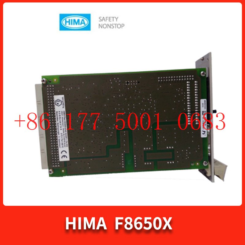
Bv7048 Digital input module HIMA
Bv7048 Digital input module HIMA
Module Clips Drive controller servo motor
Contact: Mr. Lai
Wechat:17750010683
Whats app:+86 17750010683
Skype:+86 17750010683
QQ: 3221366881
3221366881@qq.com
The integral function of the controller can also be understood in a different way, because from the plane of the transition process, the integral plays a role in moving the proportionality. The working process of the controller is combined with the above, and then the influence of integration contrast is shown in Figure 1. When the controller has an integration effect, under the action of the step signal, the output of the controller first jumps and then slowly rises until it reaches the limit output value. The first jump in output is due to the effect of proportion, while the slow increase is due to the influence of integration. If the influence of proportion is removed, the dotted line in Figure 1 represents the effect of pure integration. The effect of proportional integration on the controller output is shown by the solid line in the figure, which means that the integration effect is equivalent to slowly moving the proportional effect upwards, that is, the proportional degree continuously moves in the direction of overcoming the deviation, and the speed of movement is inversely proportional to the integration time. Only when the measured value returns to the given value and the deviation is zero, The integral only stops pushing the proportionality. If you want to move the proportionality in the opposite direction, the integration only starts to move the proportionality in the opposite direction after the measured value exceeds the given deviation in the opposite direction. Bv7048 Digital input module HIMA
Figure 1 Schematic diagram of the impact of integral contrast on sample size
The impact of positive and negative deviations on the output of the controller is shown in Figure 2. The centerline of the proportional degree in the figure corresponds to the output of the controller at the control point. When there is only proportional action, the output is a constant, that is, the centerline of the proportional degree does not change. When the integration effect is added, the centerline changes over time, and the speed of change is inversely proportional to the integration time. At this point, the output of the controller is the sum of proportional output and integral output: the integral output is the centerline of this change, so the total output is represented as a strip centered around the control point.
Figure 2 Impact of Deviation on Controller Output Bv7048 Digital input module HIMA
However, it should be pointed out that the so-called pushing or moving of the Billy degree is just a visual metaphor to illustrate the interrelationship between integral and proportional control laws, and its purpose is to facilitate learning and understanding of the role of integral. This representation method may be easier to understand the essence of integral action than abstract definitions and mathematical formulas. Finally, a summary of the integration effect is made: the integration effect of the controller is set to eliminate the residual error of the control system: the output change of the integration effect is proportional to the integration of the input deviation, and the proportional effect tightly connects the output and the measured value through the deviation. The integration effect can make the output any direct, and only stop the integration effect when the deviation is zero. This feature can eliminate the residual error, As long as the deviation exists, the integration effect will cause the output to change in the direction of eliminating the residual error.
Measuring the integration time is to input a step signal to the proportional integral controller, record the value of the vertical rise output, and start timing with a stopwatch. When the output reaches twice the vertical rise part, stop timing. At this point, the time recorded by the stopwatch is the integration time Ti, and its process is shown in Figure 3 as follows: the period of time when the output of the integration action is equal to the output of the proportional action is the integration time Ti.
The integral function of the controller can also be understood in a different way, because from the plane of the transition process, the integral plays a role in moving the proportionality. The working process of the controller is combined with the above, and then the influence of integration contrast is shown in Figure 1. When the controller has an integration effect, under the action of the step signal, the output of the controller first jumps and then slowly rises until it reaches the limit output value. The first jump in output is due to the effect of proportion, while the slow increase is due to the influence of integration. If the influence of proportion is removed, the dotted line in Figure 1 represents the effect of pure integration. The effect of proportional integration on the controller output is shown by the solid line in the figure, which means that the integration effect is equivalent to slowly moving the proportional effect upwards, that is, the proportional degree continuously moves in the direction of overcoming the deviation, and the speed of movement is inversely proportional to the integration time. Only when the measured value returns to the given value and the deviation is zero, The integral only stops pushing the proportionality. If you want to move the proportionality in the opposite direction, the integration only starts to move the proportionality in the opposite direction after the measured value exceeds the given deviation in the opposite direction.
Figure 1 Schematic diagram of the impact of integral contrast on sample size
The impact of positive and negative deviations on the output of the controller is shown in Figure 2. The centerline of the proportional degree in the figure corresponds to the output of the controller at the control point. When there is only proportional action, the output is a constant, that is, the centerline of the proportional degree does not change. When the integration effect is added, the centerline changes over time, and the speed of change is inversely proportional to the integration time. At this point, the output of the controller is the sum of proportional output and integral output: the integral output is the centerline of this change, so the total output is represented as a strip centered around the control point.
Figure 2 Impact of Deviation on Controller Output
However, it should be pointed out that the so-called pushing or moving of the Billy degree is just a visual metaphor to illustrate the interrelationship between integral and proportional control laws, and its purpose is to facilitate learning and understanding of the role of integral. This representation method may be easier to understand the essence of integral action than abstract definitions and mathematical formulas. Finally, a summary of the integration effect is made: the integration effect of the controller is set to eliminate the residual error of the control system: the output change of the integration effect is proportional to the integration of the input deviation, and the proportional effect tightly connects the output and the measured value through the deviation. The integration effect can make the output any direct, and only stop the integration effect when the deviation is zero. This feature can eliminate the residual error, As long as the deviation exists, the integration effect will cause the output to change in the direction of eliminating the residual error.
Measuring the integration time is to input a step signal to the proportional integral controller, record the value of the vertical rise output, and start timing with a stopwatch. When the output reaches twice the vertical rise part, stop timing. At this point, the time recorded by the stopwatch is the integration time Ti, and its process is shown in Figure 3 as follows: the period of time when the output of the integration action is equal to the output of the proportional action is the integration time Ti.
Time proportional control is developed on the basis of positional control, and it still relies on the switch action of the relay to achieve control. Position control only has two states: “on” and “off”, and its output is either 100% or 0%. If we find a way to make the relay periodically turn on and off near the given temperature value, and make the time of turning on and off change with the temperature deviation, it can play the role of continuously controlling the heating current. At this point, the sum of the relay contact making time and breaking time is called the action cycle T, and the ratio of the contact making time T1 to the action cycle T is the time ratio ρ, Namely:
In the formula, T1 is the contact making time of the relay; T2 is the opening time of the relay contact.
This time ratio ρ Corresponding to the power of the input heater. If the controller achieves temperature rise ρ Reduce to reduce the contact making time T1 and increase the contact breaking time T2; If the temperature drops ρ Increasing the contact making time T1 increases and the contact breaking time T2 decreases, achieving the purpose of temperature control. This control method is time proportional control. The percentage of the range that can have a proportional effect on the full scale is called the proportional band. Figure 1 shows the relationship between time ratio and temperature deviation. Generally, when the temperature deviation is zero, that is, when the actual temperature is given and T1=T2, it is equivalent to 50% of the average heating power. When the temperature is higher than the given value, ρ When the value decreases, T1<T2 is equivalent to an average heating power of less than 50%. When the temperature is below the given value, ρ When the value increases, T1>T2 is equivalent to an average heating power greater than 50%.
Figure 1 Relationship between time ratio and temperature deviation
Although the time proportional control method is still the on/off of relay contacts, due to its short action cycle relative to the heated thermal inertia, and the on/off time ratio changing with temperature deviation, it can stabilize the temperature at a required value. Its control effect is better than positional control, but there are also shortcomings in the time ratio. If there is a static error during application, it is necessary to readjust the given value.
The above analysis takes the dynamic coil instrument as an example. How does the temperature controller output by the relay work? The time ratio output of the temperature controller output by the relay is also achieved by adjusting the on/off ratio of the internal relay. The output value is proportional to the duty cycle of the square wave, adjustable from 0% -100%, and the output limit value can be set arbitrarily between 0% -100%. However, the action of the output relay is controlled by the output signal of the temperature controller. It can be said that the time ratio of the temperature controller output by the relay is also significantly different from that of the dynamic coil instrument.
In practical applications, a temperature controller with time proportional control is selected to control the heating of the electric furnace wire. If the temperature control error is required to be small, the temperature controller will obtain the best parameters through self tuning. At this time, the temperature controller will control the relay action very frequently when the actual temperature is close to the set temperature value. Only frequent action can ensure that the temperature is not overshoot or undershoot, which will sharply shorten the contact life of the contactor. How to handle this issue? Yunrun Instrument engineers suggest using SSR solid-state relays to drive voltage output temperature controllers, allowing the temperature controller to control the action of the solid-state relay to achieve control purposes. However, this approach still has its limitations, as solid-state relays allow for low operating currents and cannot meet the requirements of high-power heating equipment.
1.Has been engaged in industrial control industry for a long time, with a large number of inventories.
2.Industry leading, price advantage, quality assurance
3.Diversified models and products, and all kinds of rare and discontinued products
4.15 days free replacement for quality problems
ABB — AC 800M controller, Bailey, PM866 controller, IGCT silicon controlled 5SHY 3BHB01 3BHE00 3HNA00 DSQC series
BENTLY — 3500 system/proximitor, front and rear card, sensor, probe, cable 3500/20 3500/61 3500/05-01-02-00-001 3500/40M 176449-01 3500/22M 138607-01
Emerson — modbus card, power panel, controller, power supply, base, power module, switch 1C31,5X00, CE400, A6500-UM, SE3008,1B300,1X00,
EPRO — PR6423 PR6424 PR6425 PR6426 PR9376 PR9268 Data acquisition module, probe, speed sensor, vibration sensor
FOXBORO — FCP270 FCP280 FCM10EF FBM207 P0914TD CP40B FBI10E FBM02 FBM202 FBM207B P0400HE Thermal resistance input/output module, power module, communication module, cable, controller, switch
GE —- IS200/215/220/230/420 DS200/215 IC693/695/697/698 VMICPCI VMIVME 369-HI-R-M-0-0-E 469 module, air switch, I/O module, display, CPU module, power module, converter, CPU board, Ethernet module, integrated protection device, power module, gas turbine card
HIMA — F3 AIO 8/4 01 F3231 F8627X Z7116 F8621A 984862160 F3236 F6217 F7553 DI module, processor module, AI card, pulse encoder
Honeywell — Secure digital output card, program module, analog input card, CPU module, FIM card
MOOG — D136-001-007 Servo valve, controller, module
NI — SCXI-1100 PCI – PXIE – PCIE – SBRIO – CFP-AO-210 USB-6525 Information Acquisition Card, PXI Module, Card
Westinghouse — RTD thermal resistance input module, AI/AO/DI/DO module, power module, control module, base module
Woodward — 9907-164 5466-258 8200-1300 9907-149 9907-838 EASYGEN-3500-5/P2 8440-2145 Regulator, module, controller, governor
YOKOGAWA – Servo module, control cabinet node unit
Main products:
PLC, DCS, CPU module, communication module, input/output module (AI/AO/DI/DO), power module, silicon controlled module, terminal module, PXI module, servo drive, servo motor, industrial display screen, industrial keyboard, controller, encoder, regulator, sensor, I/O board, counting board, optical fiber interface board, acquisition card, gas turbine card, FIM card and other automatic spare parts


