")
Description
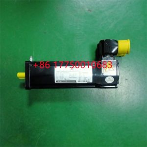
SH140/30330/0/0/02/00/10/10/00 Motor parameter settings
SH140/30330/0/0/02/00/10/10/00 Motor parameter settings
Module Clips Drive controller servo moto
SH140/30330/0/0/02/00/10/10/00 Motor is a device that converts electrical energy into mechanical energy.
It uses energized coils (i.e. stator windings) to generate a rotating magnetic field and applies it to the rotor (such as a squirrel cage closed aluminum frame) to form a magnetic electric rotational torque.
SH140/30330/0/0/02/00/10/10/00 Electric motors are divided into DC motors and AC motors according to their power sources. Most electric motors in the power system are AC motors,
which can be synchronous motors or asynchronous motors (the stator magnetic field speed and rotor rotation speed of the motor do not maintain synchronous speed).
The SH140/30330/0/0/02/00/10/10/00 electric motor is mainly composed of a stator and a rotor. The direction of force movement of the energized wires in the magnetic field is related to the direction
of the current and the direction of the magnetic field lines (magnetic field direction). The working principle of an electric motor is that the magnetic field exerts force on the current, causing the motor to rotate.
Contact: Mr. Lai
Wechat:17750010683
Whats app:+86 17750010683
Skype:+86 17750010683
QQ: 3221366881
3221366881@qq.com
2.3Smart component creation
Call the Rotator component: This component is used to allow the rotatable grinding rotor to rotate during simulation to simulate the real grinding scene. In the parameters of the Rotator component, set the reference to object, the reference object to the frame l, and the object to a copy of the rotor. (2) The rotary grinding rotor can be rotated, and the speed is l20mm/s (the speed of the grinding head will affect the quality of the finished product) ), the reference center axis is: axis (based on frame l, centerpoint x, y,: set to 0, 0, 0, Axis set x, y,: 0, 0, l000mm).
Call the Attach component: This component is used to allow the rotatable grinding rotor to be integrated with the tool body. When the tool body is installed on the flange, it can follow the movement of the flange. In the parameters of the Attach component, set the sub-object to be a copy of the rotor (2) for the rotatable polishing rotor, and the parent object is the tool body of a copy of the rotor. The offset and orientation are based on the offset of point B relative to the origin. For setting, you can use the measurement tool in Robotstudio software to measure, and then set the parameters after measurement.
Verification: Install a copy of the rotor tool body onto the robot flange, and then click Execute in the Attach component. You can observe whether the position of the rotatable grinding rotor is correct at this time. If there is a deviation, adjust the position in time, as shown in the figure. 5 shown.
Figure 5 Tool installation
2.4 Create tool coordinate system
Use the six-point method to create the tool coordinate system Too1data on the robot teach pendant at the center of the rotor. Change the tool coordinate system to Too1data in the basic options. At this time, click on the robot manual linear and you can drag the robot to move linearly at will.
2.5 Creating trajectories and programming
Determine the trajectory: According to the requirements of the work task, design the grinding trajectory around the workpiece and determine the trajectory points and transition points required for the grinding trajectory. The grinding action process is shown in Figure 6.
Setting I/O and programming: Yalong IY-l3-LA industrial robot deburring and grinding system control and application equipment adopts 0sDC-52 6/o communication board, the address is 10, Do1 is the digital output signal, the address is 1 . First set the I/O board, then set the I/O digital output signal Di1, and then program on the simulation teaching pendant. The procedure is as follows:
PRoCmain()
setDo1: Set the Do1 signal to allow the external grinding rotor to start rotating.
waitTime1: The robot stays in place and does not move, waits for 1s, and lets the polishing rotor turn to the specified speed, transition
MoveAbsjjpos10NoEoffs,v1000,z50,Too1data1: The robot moves to the initial point jpos10 above point p10. Point jpos10 is used as the starting point and end point of the robot’s action.
Move4p10,v1000,z50,Too1data1: Move straight line grinding to point p10
Move4pL0,v1000,z50,Too1data1: Move straight line grinding to pL0 point
Move4p30,v1000,z50,Too1data1: Move straight line grinding to point p30
Move4p40,v1000,z50,Too1data1: Move straight line grinding to p40 point
Move4p10,v1000,z50,Too1data1: Move straight line grinding to point p10
MoveAbsjjpos10NoEoffs,v1000,z50,Too1data1: The robot moves to the initial point jpos10 above point p10
waitTime1: wait 1s, transition
ResetDo1: Reset the Do1 signal to stop the rotor ENDPRoC
2.6 Simulation design and verification
Simulation design: Create a smart component to input the Di1 signal, and use the Di1 signal to simulate the external polishing start signal to execute the Rotator component and Attach component of the smart component to achieve the visual effect of rotating and polishing the polishing rotor. In the workstation logic design, the smart component input Di1 signal is associated with the robot Do1 signal, so that the robot signal Do1 can control the smart component input Di1 signal, thereby controlling the start and stop of the rotation of the polishing rotor.
Verification: In the program of the teaching pendant, first set the pp command to move to Main, and then set the robot startup mode to automatic. Click play in the simulation of Robotstudio software to verify whether the trajectory is consistent with the assumption, and optimize the path in time for problems existing in the simulation.
3Summary and outlook
This design is based on the programming simulation of the Yalong Y4-1360A industrial robot deburring system to control the grinding robot workstation. It covers aspects such as creating a workstation, setting up tools, creating smart components, creating tool coordinate systems, creating trajectories, programming, simulation design, and verification. Starting with it, the polishing simulation of the workstation is realized through the smart component function of Robotstudio software. The animation effect is intuitive and lifelike, which not only facilitates teaching demonstrations, but also facilitates program debugging, and has application value for both production and teaching.
In the planning and design of the workpiece grinding trajectory, according to the different roughness and grinding amount process requirements of the workpiece, the rotation speed, feed speed, feed amount, and grinding angle of the grinding rotor are also different. The feed amount can be adjusted in time according to the on-site conditions. , feed speed, rotor speed, grinding angle and other parameters. After appropriate adjustments, the motion trajectory is written with the corresponding program on the Robotstudio software to further reduce the possibility of robot collisions and singular points contained in the trajectory during the actual debugging process. ,Optimize paths and improve debugging efficiency.
200350-02-00-CN 200350 Accelerometer
IC693MDL930G relay output module
MVME162P-344S dual-height VME module
DS3815PAHB1A1A Printed circuit board
CC-PDIH01 Digital input module
330130-045-01-00 3300 XL Extension cable
MVME162-510A Embedded controller
IC200MDL750G high-density digital output module
SAIA-BURGES PCD2.W600 PCD2W600 ANALOG OUTPUT
PM861AK01 3BSE018157R1 Processor Unit
GE IC697BEM733 I/O scanner
IC697MDL653 GE Logic input module
GE IC697RCM711 Redundant communication module
GE IC697MDL740
ICS TRIPLEX T8461 Digital Output Module
1X00416H01 EMERSON Power distribution module
ABB PM866K01 3BSE050198R1 Processor Unit Kit
MOTOROLA MVME2434 VME Processor Module
ABB CI858K01 3BSE018135R1 DriveBus Interface
ABB RDCU-12C+CABLES DRIVE CONTROL UNIT
ABB SDCS-PIN48-SD PULSE TRANSFORMER BOARD
KONGSBERG RCU502 REMOTE CONTROLLER UNIT
ABB 3BHL000986P7000 LXN1604-6 AC/DC converter
ALLEN-BRADLEY 2711-T5A8L1
ALLEN BRADLEY 2801-N22 USER INTERFACE BOX
ALLEN-BRADLEY 6176M-17PT Industrial monitor
ALLEN BRADLEY 847H-JL2C-RE01024 encoder
ALLEN-BRADLEY 842E-CM-MIP3B Encoder
JAPMC-CP2230-E Yaskawa Machine Controller
GE HYDRAN M2transformer monitoring equipment
ABB PM825 3BSE010796R1 S800 Processor
Vibro-meter VM600 IOCN input/output card for the CPUM card
Vibro-meter VM600 AMC8 Analog monitoring card
Vibro-meter VM600 RLC16 Trunk card
Vibro-meter VM600 XIO16T input/output module for the XMx16 module
Vibro-meter VM600 CPUR rack controller and communication interface card
Vibro-meter VM600 Mk2 / VM600 ABE056 Ultra-thin rack
Vibro-meter CPUR card VM600 IOCR input/output card
Vibro-meter VM600 AMC8 Analog monitoring card
Vibro-meter VM600 CPUM Modular CPU card
Vibro-meter VM600 MPC4 mechanical protection card
Vibro-meter VM600 XMV16 Vibration status monitoring module
3BDH000384R0005 AO723F analog output module
3BDH000396R0005 CI741F PROFIBUS Interface module
3BDH000383R0005 DX722F Digital input/output module
3BDH000387R0005 DX731F Digital input/output module
3BDH000371R0005 DA701F Digital/Analog module
3BE066485R1 PM851AK01 Processor unit
3BE069449R1 CI854BK01 PROFIBUS-DP/V1 port
3BSE020512R1 AI801 Analog Input 8 channels
3BSE020514R1 AO801 Analog output 8 channels
3BSE020508R1 DI801 Digital input 24V 16 channels
3BSE020510R1 DO801 Digital output 24V 16 channels
3BSE013208R1 TB820V2 Modulebus Cluster modem
3BSE008508R1 DI810 Digital input module
3BSE020836R1 DI840 Redundant digital input module
3BSC690073R1 DI890 The digital input module is intrinsically secure
3BSE008510R1 DO810 Digital output module Transistor type
3BSE020838R1 DO840 Redundant digital output module transistor type
3BDH000530R1 PM803F Base Unit 16 MB
3BDH008381R0001 TU732F Input/output terminal device
3BSE076940R1 PM 862K01 Processor Unit -67MHz and 32MB.
1.Has been engaged in industrial control industry for a long time, with a large number of inventories.
2.Industry leading, price advantage, quality assurance
3.Diversified models and products, and all kinds of rare and discontinued products
4.15 days free replacement for quality problems
ABB — AC 800M controller, Bailey, PM866 controller, IGCT silicon controlled 5SHY 3BHB01 3BHE00 3HNA00 DSQC series
BENTLY — 3500 system/proximitor, front and rear card, sensor, probe, cable 3500/20 3500/61 3500/05-01-02-00-001 3500/40M 176449-01 3500/22M 138607-01
Emerson — modbus card, power panel, controller, power supply, base, power module, switch 1C31,5X00, CE400, A6500-UM, SE3008,1B300,1X00,
EPRO — PR6423 PR6424 PR6425 PR6426 PR9376 PR9268 Data acquisition module, probe, speed sensor, vibration sensor
FOXBORO — FCP270 FCP280 FCM10EF FBM207 P0914TD CP40B FBI10E FBM02 FBM202 FBM207B P0400HE Thermal resistance input/output module, power module, communication module, cable, controller, switch
GE —- IS200/215/220/230/420 DS200/215 IC693/695/697/698 VMICPCI VMIVME 369-HI-R-M-0-0-E 469 module, air switch, I/O module, display, CPU module, power module, converter, CPU board, Ethernet module, integrated protection device, power module, gas turbine card
HIMA — F3 AIO 8/4 01 F3231 F8627X Z7116 F8621A 984862160 F3236 F6217 F7553 DI module, processor module, AI card, pulse encoder
Honeywell — Secure digital output card, program module, analog input card, CPU module, FIM card
MOOG — D136-001-007 Servo valve, controller, module
NI — SCXI-1100 PCI – PXIE – PCIE – SBRIO – CFP-AO-210 USB-6525 Information Acquisition Card, PXI Module, Card
Westinghouse — RTD thermal resistance input module, AI/AO/DI/DO module, power module, control module, base module
Woodward — 9907-164 5466-258 8200-1300 9907-149 9907-838 EASYGEN-3500-5/P2 8440-2145 Regulator, module, controller, governor
YOKOGAWA – Servo module, control cabinet node unit
Main products:
PLC, DCS, CPU module, communication module, input/output module (AI/AO/DI/DO), power module, silicon controlled module, terminal module, PXI module, servo drive, servo motor, industrial display screen, industrial keyboard, controller, encoder, regulator, sensor, I/O board, counting board, optical fiber interface board, acquisition card, gas turbine card, FIM card and other automatic spare parts