")
Description
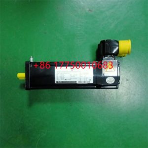
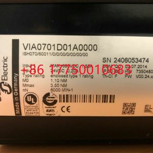
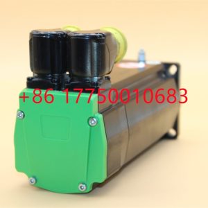
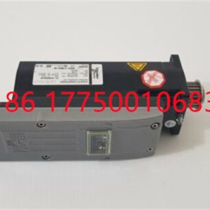
SM140/30/210/P0/45/S1/B1 Motor installation instructions
SM140/30/210/P0/45/S1/B1 Motor installation instructions
Module Clips Drive controller servo moto
SM140/30/210/P0/45/S1/B1 Motor is a device that converts electrical energy into mechanical energy.
It uses energized coils (i.e. stator windings) to generate a rotating magnetic field and applies it to the rotor (such as a squirrel cage closed aluminum frame) to form a magnetic electric rotational torque.
SM140/30/210/P0/45/S1/B1 Electric motors are divided into DC motors and AC motors according to their power sources. Most electric motors in the power system are AC motors,
which can be synchronous motors or asynchronous motors (the stator magnetic field speed and rotor rotation speed of the motor do not maintain synchronous speed).
The SM140/30/210/P0/45/S1/B1 electric motor is mainly composed of a stator and a rotor. The direction of force movement of the energized wires in the magnetic field is related to the direction
of the current and the direction of the magnetic field lines (magnetic field direction). The working principle of an electric motor is that the magnetic field exerts force on the current, causing the motor to rotate.
Contact: Mr. Lai
Wechat:17750010683
Whats app:+86 17750010683
Skype:+86 17750010683
QQ: 3221366881
3221366881@qq.com
2.3Smart component creation
Call the Rotator component: This component is used to allow the rotatable grinding rotor to rotate during simulation to simulate the real grinding scene. In the parameters of the Rotator component, set the reference to object, the reference object to the frame l, and the object to a copy of the rotor. (2) The rotary grinding rotor can be rotated, and the speed is l20mm/s (the speed of the grinding head will affect the quality of the finished product) ), the reference center axis is: axis (based on frame l, centerpoint x, y,: set to 0, 0, 0, Axis set x, y,: 0, 0, l000mm).
Call the Attach component: This component is used to allow the rotatable grinding rotor to be integrated with the tool body. When the tool body is installed on the flange, it can follow the movement of the flange. In the parameters of the Attach component, set the sub-object to be a copy of the rotor (2) for the rotatable polishing rotor, and the parent object is the tool body of a copy of the rotor. The offset and orientation are based on the offset of point B relative to the origin. For setting, you can use the measurement tool in Robotstudio software to measure, and then set the parameters after measurement.
Verification: Install a copy of the rotor tool body onto the robot flange, and then click Execute in the Attach component. You can observe whether the position of the rotatable grinding rotor is correct at this time. If there is a deviation, adjust the position in time, as shown in the figure. 5 shown.
Figure 5 Tool installation
2.4 Create tool coordinate system
Use the six-point method to create the tool coordinate system Too1data on the robot teach pendant at the center of the rotor. Change the tool coordinate system to Too1data in the basic options. At this time, click on the robot manual linear and you can drag the robot to move linearly at will.
2.5 Creating trajectories and programming
Determine the trajectory: According to the requirements of the work task, design the grinding trajectory around the workpiece and determine the trajectory points and transition points required for the grinding trajectory. The grinding action process is shown in Figure 6.
Setting I/O and programming: Yalong IY-l3-LA industrial robot deburring and grinding system control and application equipment adopts 0sDC-52 6/o communication board, the address is 10, Do1 is the digital output signal, the address is 1 . First set the I/O board, then set the I/O digital output signal Di1, and then program on the simulation teaching pendant. The procedure is as follows:
PRoCmain()
setDo1: Set the Do1 signal to allow the external grinding rotor to start rotating.
waitTime1: The robot stays in place and does not move, waits for 1s, and lets the polishing rotor turn to the specified speed, transition
MoveAbsjjpos10NoEoffs,v1000,z50,Too1data1: The robot moves to the initial point jpos10 above point p10. Point jpos10 is used as the starting point and end point of the robot’s action.
Move4p10,v1000,z50,Too1data1: Move straight line grinding to point p10
Move4pL0,v1000,z50,Too1data1: Move straight line grinding to pL0 point
Move4p30,v1000,z50,Too1data1: Move straight line grinding to point p30
Move4p40,v1000,z50,Too1data1: Move straight line grinding to p40 point
Move4p10,v1000,z50,Too1data1: Move straight line grinding to point p10
MoveAbsjjpos10NoEoffs,v1000,z50,Too1data1: The robot moves to the initial point jpos10 above point p10
waitTime1: wait 1s, transition
ResetDo1: Reset the Do1 signal to stop the rotor ENDPRoC
2.6 Simulation design and verification
Simulation design: Create a smart component to input the Di1 signal, and use the Di1 signal to simulate the external polishing start signal to execute the Rotator component and Attach component of the smart component to achieve the visual effect of rotating and polishing the polishing rotor. In the workstation logic design, the smart component input Di1 signal is associated with the robot Do1 signal, so that the robot signal Do1 can control the smart component input Di1 signal, thereby controlling the start and stop of the rotation of the polishing rotor.
Verification: In the program of the teaching pendant, first set the pp command to move to Main, and then set the robot startup mode to automatic. Click play in the simulation of Robotstudio software to verify whether the trajectory is consistent with the assumption, and optimize the path in time for problems existing in the simulation.
3Summary and outlook
This design is based on the programming simulation of the Yalong Y4-1360A industrial robot deburring system to control the grinding robot workstation. It covers aspects such as creating a workstation, setting up tools, creating smart components, creating tool coordinate systems, creating trajectories, programming, simulation design, and verification. Starting with it, the polishing simulation of the workstation is realized through the smart component function of Robotstudio software. The animation effect is intuitive and lifelike, which not only facilitates teaching demonstrations, but also facilitates program debugging, and has application value for both production and teaching.
In the planning and design of the workpiece grinding trajectory, according to the different roughness and grinding amount process requirements of the workpiece, the rotation speed, feed speed, feed amount, and grinding angle of the grinding rotor are also different. The feed amount can be adjusted in time according to the on-site conditions. , feed speed, rotor speed, grinding angle and other parameters. After appropriate adjustments, the motion trajectory is written with the corresponding program on the Robotstudio software to further reduce the possibility of robot collisions and singular points contained in the trajectory during the actual debugging process. ,Optimize paths and improve debugging efficiency.
Display operation panel 3BHE039426R0101 UFC912A101
Display operation panel 3BHE039203R0101 GVC736CE101
Display operation panel 3BHE039203R0101
Display operation panel 3BHE037864R0106
Display operation panel 3BHE037864R0106
Display operation panel 3BHE035301R0003
Display operation panel 3BHE035301R0001
Display operation panel 3BHE033067R0101
Display operation panel 3BHE032285R0102 XVC772A102
Display operation panel 3BHE032285R0102
Display operation panel 3BHE032025R0101
Display operation panel 3BHE031065R0020
Display operation panel 3BHE029110R0111
Display operation panel 3BHE029110R0111
Display operation panel 3BHE028959R0101 PPC902CE101
Display operation panel 3BHE028761R1002
Display operation panel 3BHE028761R1001
Display operation panel 3BHE027859R0102 DDC779CE102
Display operation panel 3BHE026284R0102
Display operation panel 3BHE024855R1101
Display operation panel 3BHE024855R0101
Display operation panel 3BHE024855R0101
Display operation panel 3BHE024577R0101 PPC907BE
Display operation panel 3BHE024577R0101 HIEE401807R0001
Display operation panel 3BHE024577R0101
Display operation panel 3BHE024577R0101
Display operation panel 3BHE024415R0101
Display operation panel 3BHE023584R2025
Display operation panel 3BHE022455R1101
Display operation panel 3BHE022333R0101
Display operation panel 3BHE022294R0101 GFD233
Display operation panel 3BHE022294R0101
Display operation panel 3BHE022287R0001
Display operation panel 3BHE021951R0124
Display operation panel 3BHE021951R0124
Display operation panel 3BHE021889R0101 UFC721BE101
Display operation panel 3BHE021889R0101
Display operation panel 3BHE021887R0101
Display operation panel 3BHE021083R0101 XVC770BE101
Display operation panel 3BHE021083R0101 XVC770BE101
Display operation panel 3BHE020455R0103
Display operation panel 3BHE020356R0101
Display operation panel 3BHE019719R0101 GVC736BE101
Display operation panel 3BHE017628R0102
Display operation panel 3BHE014967R0002 UNS2880B-P,V2
Display operation panel 3BHE014658R0102
Display operation panel 3BHE014185R0002
Display operation panel 3BHE014185R0001 UUD148AE01
Display operation panel 3BHE014185R0001
Display operation panel 3BHE014185R0001
Display operation panel 3BHE014105R0001 5SHY3545L0020
Display operation panel 3BHE014105R0001
Display operation panel 3BHE014023R0101 UFC789AE101
Display operation panel 3BHE013299R0002 LTC743CE02
Display operation panel 3BHE013299R0002
Display operation panel 3BHE010751R0101
Display operation panel 3BHE009949R0004
Display operation panel 3BHE009949R0004
Display operation panel 3BHE009681R0101
Display operation panel 3BHE009681R0101
Display operation panel 3BHE009681R0101
Display operation panel 3BHE009319R0001
Display operation panel 3BHE009017R0102 XVC724BE102
Display operation panel 3BHE009017R0102
Display operation panel 3BHE006805R0002 DDC779BE02
Display operation panel 3BHE006412R0101 UFC762AE101
Display operation panel 3BHE006412R0101 CVMI2B
Display operation panel 3BHE006412R0101
Display operation panel 3BHE006373R0101 XVC769AE101
Display operation panel 3BHE006373R0101 XVC769AE101
Display operation panel 3BHE004573R0145
Display operation panel 3BHE004573R0145
1.Has been engaged in industrial control industry for a long time, with a large number of inventories.
2.Industry leading, price advantage, quality assurance
3.Diversified models and products, and all kinds of rare and discontinued products
4.15 days free replacement for quality problems
ABB — AC 800M controller, Bailey, PM866 controller, IGCT silicon controlled 5SHY 3BHB01 3BHE00 3HNA00 DSQC series
BENTLY — 3500 system/proximitor, front and rear card, sensor, probe, cable 3500/20 3500/61 3500/05-01-02-00-001 3500/40M 176449-01 3500/22M 138607-01
Emerson — modbus card, power panel, controller, power supply, base, power module, switch 1C31,5X00, CE400, A6500-UM, SE3008,1B300,1X00,
EPRO — PR6423 PR6424 PR6425 PR6426 PR9376 PR9268 Data acquisition module, probe, speed sensor, vibration sensor
FOXBORO — FCP270 FCP280 FCM10EF FBM207 P0914TD CP40B FBI10E FBM02 FBM202 FBM207B P0400HE Thermal resistance input/output module, power module, communication module, cable, controller, switch
GE —- IS200/215/220/230/420 DS200/215 IC693/695/697/698 VMICPCI VMIVME 369-HI-R-M-0-0-E 469 module, air switch, I/O module, display, CPU module, power module, converter, CPU board, Ethernet module, integrated protection device, power module, gas turbine card
HIMA — F3 AIO 8/4 01 F3231 F8627X Z7116 F8621A 984862160 F3236 F6217 F7553 DI module, processor module, AI card, pulse encoder
Honeywell — Secure digital output card, program module, analog input card, CPU module, FIM card
MOOG — D136-001-007 Servo valve, controller, module
NI — SCXI-1100 PCI – PXIE – PCIE – SBRIO – CFP-AO-210 USB-6525 Information Acquisition Card, PXI Module, Card
Westinghouse — RTD thermal resistance input module, AI/AO/DI/DO module, power module, control module, base module
Woodward — 9907-164 5466-258 8200-1300 9907-149 9907-838 EASYGEN-3500-5/P2 8440-2145 Regulator, module, controller, governor
YOKOGAWA – Servo module, control cabinet node unit
Main products:
PLC, DCS, CPU module, communication module, input/output module (AI/AO/DI/DO), power module, silicon controlled module, terminal module, PXI module, servo drive, servo motor, industrial display screen, industrial keyboard, controller, encoder, regulator, sensor, I/O board, counting board, optical fiber interface board, acquisition card, gas turbine card, FIM card and other automatic spare parts